Octal Mojo guitar amp (DIY)
Schematics
|
|
Preface(by Tom Schlangen)The following circuit pretty much resembles a Fender Champ type AA764, with a few noteworthy exceptions:
So, basically we have an all-octal, all triode variant of the Fender Champ here. Deviations from the original are rather small, since - who would have wondered - almost half a century of improving this circuit at the Fender factory doesn´t leave much to do.
|
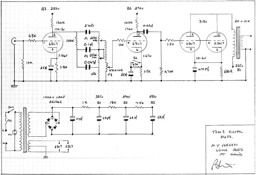
The schematic(by Paul Stanley)
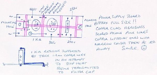
PSU board layout
|
Some notes on the circuit(by Tom Schlangen)
12AX7, 6SL7 and relative stage gainSome keen readers may argue from paper that using 6SL7 (μ = 70) will give much less gain (and distortion) than when using ECC83/12AX7 (μ = 100) like with the original Champ type AA764 circuit. Actually, this is not the case, because:
In short, the 6SL7 front end and driver stages, have more than double the relative gain feeding the 6SN7 power stage, than those ECC83 based front end and driver stages feeding a 6V6 beam power tube stage like with the original Champ type AA764 circuit.
The "gain boost" switchOur circuit features a "gain boost" switch, which actually should be viewed as a "gain reduction" switch, because, as shown before, the relative gain into the 6SN7 power stage is so much higher, that the standard position ("standard" as compared to the AA764 circuit, which has the driver cathode resistor bypassed, not switchable), would give way to much sensitivity, gain and distortion.Opening the switch, so that the driver stage cathode resistor is not bypassed, actually lowers the gain of this stage to an overall and relative ammount of gain that makes it comparable to the Fender AA764 circuit again.
Essentially, calling it either a "gain boost" or a "gain reduction" switch is moot, of couse - it is just a matter of personal
preferences and music style
The output transformerSince the combined iddle current of the paralleled 6SN7 sections power stage is rather low (about 15-16mA in total), it was not necessary to use output iron designed for 6V6 or EL84/6BQ5 power class tubes. Instead, an output transformer of considerably smaller core size could be used. In the end, a suitable unit from a german Nordmende table top radio was chosen and bought via Ebay for less than a dozen Euros. One small problem showed up with this OPT: While the printing on this unit says it has a reflected impedance of 7kΩ, I actually measured it to be more in 5-5,5 kΩ range. This would be too low a reflected impedance for the paralleled 6SN7 sections to keep them happy. Fortunately this OPT features both 4Ω and 8Ω taps at the secondary, so the nominal 8Ω speaker was wired to the 4Ω tap of the transformer to give a reflected impedance of 10-11kΩ, which is ideal for the paralleled section 6SN7 flea power stage - voila!
Further usage ideasAt about 1 WRMS output power, the 6SN7 anode voltage swings from about 130V to about 425V, which covers a total swing of almost 300 Vpeak-peak. Thinking about it, this little amp circuit would happily excite even the most demanding monster power SE tubes used as "afterburners", as long they don´t need grid current drive (class A2 operation). Considering this, and how good this small amp circuit sounds, this could lead to a most interesting project - use the amp circuit as is at home and for practice, and kick in the "BIG FINALS" (a couple of 300Bs in parallel would do nicely) when on stage ... In such a setup, the 1 Watt output should be kept working into a dummy load instead of a speaker. Alternatively, if the flea-power output is not wanted or needed, the small OPT could be replaced by a suitable choke. But that somewhat would compromise the idea of a "complete amp within an amp", of course.
|